Comparison of Methods to Determine Tearing Resistance Curves in SENB Specimens
By Philippa Moore and Alex Pargeter
Industrial Need
There are three main standards which describe the fracture toughness testing of ductile alloys by generating tearing resistance curves: BS 7448-4 (1997), ISO 12135 (2016) and ASTM E1820 (2018). These standards share much in common in their overall approach, but they differ in significant details relating to the generation and analysis of the test data. In order to understand the significance of the differences, this report reviews a range of techniques and methods given in these standards for the determination of tearing resistance curves (R-curves) in single-edge notched bend (SENB) fracture toughness test specimens. It compares the various R-curves produced based on quasi-static tests in air and room temperature.
ASTM E1820, 2018: ‘Standard Measurement of Fracture Toughness’, ASTM.
BS 7448-4, 1997: ‘Fracture mechanics toughness tests — Part 4: Method for determination of fracture resistance curves and initiation values for stable crack extension in metallic materials’, British Standards Institution.
ISO 12135, 2016: ‘Metallic materials - Unified method of test for the determination of quasi-static fracture toughness’. ISO.
Key findings
- Consistent J R-curves were determined when testing SENB specimens to ASTM E1820, BS 7448-4 or ISO 12135.
- Determination of crack extension was similar when using unloading compliance, when using direct current potential drop (DCPD), or when using the normalisation method.
- The tearing correction for J will cause some difference between the standard methods, depending on the level of crack extension and the increments of crack extension measurement.
- Crack tip opening displacement (CTOD) R-curves based on rigid rotation gave consistently higher results than when CTOD was determined from J.
- The unloading compliance function based on load line displacement (LLD) performed poorly in relation to other methods, giving only relative crack measurements rather than absolute values of instantaneous crack length, and giving the most scatter in the resulting R-curves.
- The use of clip gauges to determine CMOD can be challenging under dynamic conditions or in aggressive environments. In these cases, J determined from LLD using ram correction will give a suitable alternative value of J, while DCPD or the normalisation method may be used to determine crack extension.
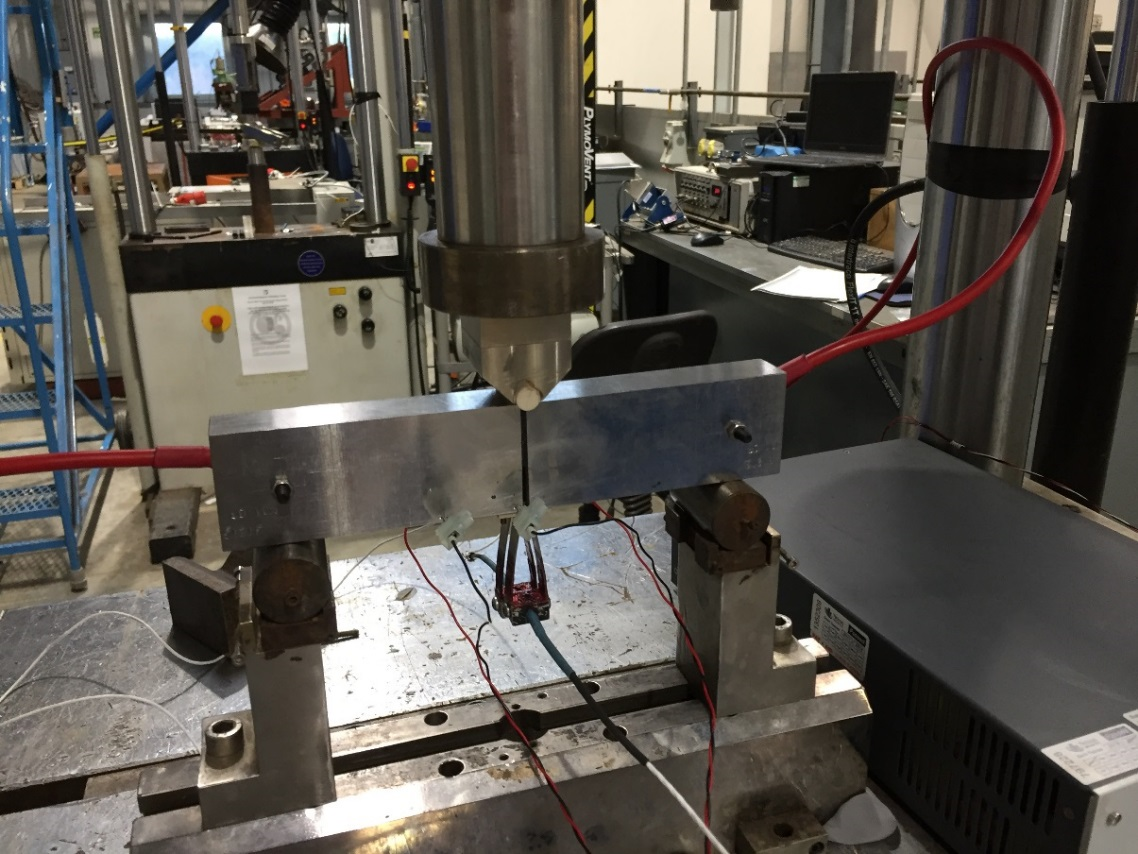
Side-grooved specimen set up with double clip gauge and DCPD measurements
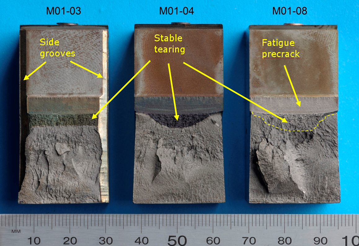
Fracture faces from specimen with side-grooves (M01-03) and plane-sided specimens (M01-04 and M01-08), showing the shape of the tearing
