Experimental Study and Prediction of Fatigue Crack Growth in Girth Welded Pipes
Yan H. Zhang, Stephen J Maddox and G Reza Razmjoo TWI Ltd
Paper OMAE2002-28595 presented at OMAE:2002 Offshore Mechanics and Arctic Engineering Conference, 23-28 June 2002, Oslo, Norway.
Abstract
Fracture mechanics fatigue crack growth analysis is widely used in the Engineering Critical Assessment of welded structures. An important requirement is an accurate solution for the stress intensity factor, K, for the particular type and geometry of crack under consideration. A case commonly encountered is the weld toe crack. A solution incorporating the stress intensity magnification factor, M
k, to allow for the stress concentration effect of the welded joint, based on 2D FEA has been in use for many years. A new solution from 3D FEA has recently become available. However, in both cases, little has been done to validate the solutions against actual fatigue crack growth data. The results from a recent investigation of fatigue in large diameter (609mm OD x 20mm WT) girth-welded pipes provided an opportunity to do this. This paper presents a comparison of these crack growth data based on beachmarking information with predictions based on the 2D and 3D M
k solutions.
It was found that the 2D M k solution tended to over-estimate the crack growth rate, while the 3D solution provided better correlation between predicted and actual crack propagation behaviour. It is therefore recommended that the 3D M k solution should be used in the calculation of K for weld toe cracks.
Introduction
Currently fatigue design in welded structures is mainly based on S-N curves contained in codes such as BS7608 [1993]
[4] , DNV [2000]
[6] , API [1993]
[1] . However, there is also the need to determine the tolerance of welded structures to flaws, to ensure that premature failure will not occur before the critical crack size is reached and to model the fatigue life in general, for example to establish in-service inspection intervals. Since the fatigue lives of most welded structures consist mainly of the growth of cracks from pre-existing imperfections, such Engineering Critical Assessment (ECA) can be performed using fracture mechanics-based fatigue crack growth analysis. A widely used approach is that contained in BS 7910 [2000]
[5] . This entails integrating the relationship between rate of crack growth da/dN and the stress intensity factor range ΔK, which in its simplest form is the Paris law:
da/dN = C ( ΔK) m (1)
where
ΔK = Y Δ σ √( πa) (2)
C and m are material constants, a is the crack size, Δ σ is the applied stress range and Y is a dimensionless function of geometry and loading.
To achieve accurate crack growth prediction, a reliable solution for ΔK is required. A particularly common case is fatigue cracking from a weld toe. For this, use is made of the weld toe magnification factor M k which is defined as (Maddox, 1991) [10] :
M k = K in plate with weld /K in plate without weld (3)
M k quantifies the change in stress intensity factor as a result of the presence of the welded joint. It is used in conjunction with the K-solution for the same crack in plain plate, without the welded joint, giving ΔK = M kY Δ σ √( πa). Many M k solutions have been generated for cracks at the toes of fillet and butt welds (Smith and Hurworth, 1984 [15] , Maddox and Andrews, 1990) [9] and incorporated in ECA procedures (BSI, 1991). Weld toe flaws and fatigue cracks usually adopt a semi-elliptical shape. However, most of these solutions were based on two-dimensional (2D) finite element stress analysis, because of the complexity of 3D-stress analysis. Even though they have been widely used, and indeed still form the basis of the default solution in BS 7910 [2000] [5] , it has been realised that they can overestimate ΔK and hence the crack growth rate for surface cracks [Maddox, 1997] [11] . However, with the increasing power of 3D FEA, new K solutions for weld toe cracks are appearing [e.g. Bell, 1987 [2] , Bowness and Lee 2000] [3] . The comprehensive solution produced by Bowness and Lee [2000] [3] is included in BS 7910. However, it has not been validated against experimental data.
In this paper, fatigue crack growth measurements obtained from fatigue tests on full-scale girth welded pipes [Maddox and Razmjoo, 1998] [12] are used for such validation. Crack growth from known cracks at the toes of girth welds in pipes was predicted using both 2D- and 3D-M k solutions in the calculation of DK and then compared with the experimental data to assess their accuracy.
Experimental details
Material
The test specimens were fabricated from 20mm thick by 609mm diameter steel pipe with mechanical properties similar to those of API 5L-X60, as detailed in [Maddox and Razmjoo, 1998] [12] .
Fatigue testing
The specimens were fatigue tested axially under load control with a mean tensile stress of 125 MPa. The resulting stress ratio R (minimum/maximum stress) varied from 0.1 to 0.56 depending on the applied cyclic stress range. The project involved several test series, each with a number of specimens incorporating girth welds made with different processes [Maddox and Razmjoo, 1998]
[12] . The main objective was to establish fatigue lives, but attempts were also made to monitor the development and growth of fatigue cracks. These initiated from the girth weld toe on either the outside or inside of the pipe. In all but one series (T4) the crack growth rates were determined using the beach-marking technique. For series T4, crack growth was measured directly using the alternating current potential drop (ACPD) technique.
Beachmarking was achieved by the periodic application of blocks of cycles at the same maximum stress as that used for the fatigue tests, but at a lower stress range. This method was chosen to ensure that the beachmarking operation did not influence the rate of fatigue crack growth, in particular reducing it as a result of crack growth retardation due to peak stress changes. The number of beachmarking cycles was controlled to produce a small crack depth increase, typically within the range of 1% to 5%. An example showing such beachmarks is given in Fig.1. Information about the progress of fatigue crack depth was also obtained using ultrasonic inspection.
Fig.1. Beachmarks on the fracture surface of specimen T1-3
Misalignment
An important feature of transversely loaded butt-weld joints is misalignment. The joint will try to straighten under axial loading and, as a result, local secondary stresses will be induced. The resulting increase in stress in a region local to the weld toe will, of course, influence the fatigue life achieved. A stress magnification factor, K m, is accordingly defined as the ratio of the local stress to the nominal stress. In the tests, the extra bending stress due to misalignment was determined from strain measurements on each specimen [Maddox and Razmjoo, 1998] [12] . In the fracture mechanics analysis, use was made of the two stress components, nominal axial and secondary bending, separately.
Fracture mechanics analysis
Fracture mechanics was used to model the fatigue performance of the girth welds. The Paris law crack growth relationship given in Eq.1 was integrated to predict the growth of known initial cracks, as follows:
(4)
where N is the number of cycles needed to grow a flaw of initial size a i to a final size a f under stress range Δ σ. This equation was used to calculate the progress of cracks at the toes of girth welds in the pipe specimens.
In practice, the weld toe cracks adopted a semi-elliptical shape. For such cracks, the dimension in the thickness direction is defined as 'a', while that along the weld toe is defined as '2c'. Crack growth was calculated in both the a- and c-directions for comparison with the experimental results. For such calculations using a 2D M k solution, the solution is applied directly for calculating ΔK at the deepest point in the crack. Thus, M ka decreases as 'a' increases. However, in the absence of a solution for M kc, at the ends of the crack, a constant value is assumed for assessing crack growth in the c-direction. Based on the correlation of actual and predicted fatigue lives for fillet welds in steel [Maddox, 1985] [8] , PD6493 [BSI, 1991] [14] recommended the use of the value of M ka at a=0.15mm. The same assumption was made in the present calculations based on the 2D M k.
Referring to the Paris law, use was made of the recommended values for the constants m and C for steels in BS7910 [BSI, 2000] [5] . These are m = 3.0 and mean values for C of 1.5x10 -13 for R~0.1 and 2.5x10 -13 for R ≥0.5, for ΔK expressed in Nmm -3/2 and da/dN in mm/cycle. These values were derived from a statistical evaluation of published fatigue crack growth data [King, 1998] [7] .
ΔK was calculated using the recommended solutions for Y and M k, both 2D and 3D, in BS7910 [BSI, 2000] [5] .
Results
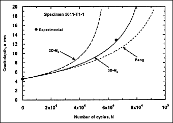
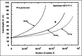
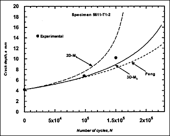
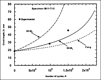
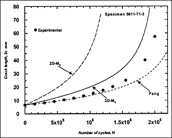
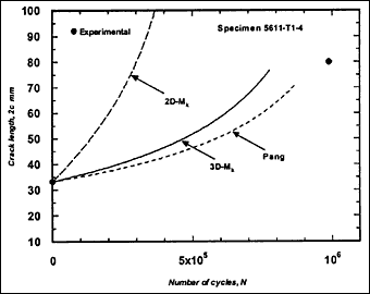
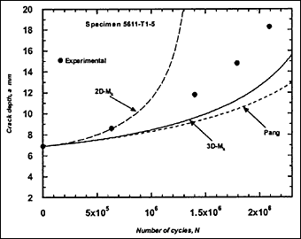
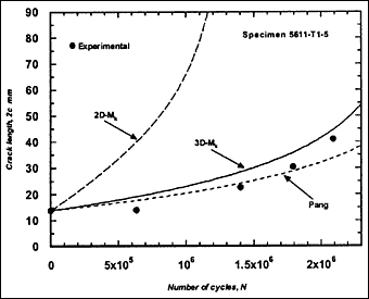
Beach-mark information, consisting of at least two marks, was available for 12 specimens. Fatigue cracking always started from weld toe, in most cases from outer surface. The resulting fatigue crack growth data are presented as crack length and depth against number of cycles in
Fig.2. Crack growth at the surface could not be determined clearly in some cases, in which case only crack depth data are included.
|
Fig.2a) Specimen T1-1, crack growth in depth and length
|
|
|
|
|
|
Fig.2b) Specimen T1-2, crack growth in depth and length
|
|
|
|
|
|
Fig.2c) Specimen T1-3, crack growth in depth and length
|
|
|

|
|
|
Fig.2d) Specimen T1-4, crack growth in depth and length
|
|
|

|
|
|
Fig.2e) Specimen T1-5, crack growth in depth and length
|
|
|
|
|
|
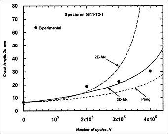
Fig.2f) Specimen T2-1, crack growth in depth and length
|
|
|

|
|
|
Fig.2g) Specimen T2-2, crack growth in depth and length
|
|
|

|

|
|
Fig.2h) Specimen T2-3, crack growth in depth
|
|
|

|
|
|
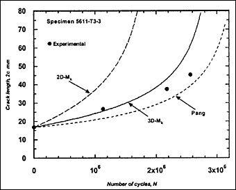
Fig.2i) Specimen T3-3, crack growth in depth and length
|
|
|

|
|
|
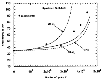
Fig.2j) Specimen T4-3, crack growth in depth and length
|
|
|

|
|
|
Fig.2k) Specimen T5-1, crack growth in depth
|
|
|

|
|
|
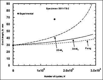
Fig.2l) Specimen T5-2, crack growth in depth and length
|
|
|

|
|
|
Fig.2m) Specimen T5-3, crack growth in depth and length
|
|
|

|
|
|
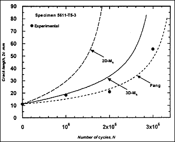
Fig.2. Comparison of experimental and predicted fatigue crack extension in depth and length (using the Paris law coefficient C=1.0x10 -13.)
|
These crack growth data were compared with predictions based on Eq.4. For each case, the prediction started with the earliest recorded crack depth (a i) and length (2c i). The local stress range, including any secondary bending stress due to misalignment, was used in the calculation of ΔK. Initially, when the appropriate recommended mean value of C was used, it was found that the crack growth predicted using the 3D-M k solution overestimated the actual in most cases. The predictions were even poorer when 2D-M k solution was used. It was thought that this reflected the fact that the crack growth characteristics of the actual steels were different from the mean crack growth laws in BS 7910. Limited tests on the pipe steels indicated that m = 3 was reasonable but that C could be as low as 1 x 10 -13, lower than the BS 7910 values. Further trial calculations indicated that this value was appropriate when the 3D-M k solution in BS 7910 was used, and therefore it was adopted for the remaining calculations.
The resulting predicted crack growth in both depth and length directions are compared with the experimental data in Fig.2. It can be seen that the 3D-M k solution gives the best prediction for growth in both directions. Generally, use of the 2D-M k solution still significantly overestimated the actual crack growth, both in the depth and length directions. It has to be borne in mind that these over-predictions were based on a C value that is below the mean value suggested in BS 7910 [2000] [5] .
By reviewing M k solutions for welds, Pang [1990] [13] showed that the assumption of a constant value of M k for crack growth in the c-direction when using the 2D ΔK solution was conservative. By curve fitting of the results from Bell's 3D-stress analysis [1987] [2] , he proposed a less conservative and simple expression for M k to be applied when assessing growth in the c-direction, M kc, for crack front shapes in the range of a/2c between 0.1 to 0.5. It was expressed as a function of M k for application to growth in the a-direction, M ka, as:
M kc = M ka + 1.15 exp (-9.74 a/B) (5)
M ka is still calculated using the 2D-M k solution. For comparison, this M k solution was also used in the calculation of ΔK to predict fatigue crack growth in the girth-welded specimens. The results are included in Fig.2, referred as Pang. It was assumed that this solution is applicable for any crack front shape. It can be seen that the prediction based on the Pang's expression is close to that obtained using the 3D-M k solution developed by Bowness and Lee [2000] [3] , with Pang's prediction of crack extension being slightly lower. The only exception, where the prediction using Pang's equation was slightly higher, is specimen T4-3. Its initial a/2c aspect ratio was very small (a = 2.3mm and 2c = 35mm), which is out of the application range of 0.1 to 0.5 for the Pang's solution [1990] [13] .
Mention should be made of the two cases, in series T5, where all M k solutions led to underestimates of the crack growth rate, specimens T5-1and T5-2 in Fig.2(k) and (l). In both cases, the crack initiated from the inside and propagated through weld metal. However, there were other cases where cracks that had initiated on the inside did not exhibit such exceptionally high growth rates. It is possible that crack growth in these two specimens was affected by local welding defects, but a full explanation has not been found. The results might simply be a reflection of scatter in fatigue crack growth rates. It may be noted that use of the mean value of C for R ≥0.5 recommended in BS 7910, that is C = 2.5x10 -13, always over-estimated the actual crack growth rate, the predictions based on the 2D-M k being excessively conservative, see one example in Fig.3.
Fig.3. Comparison of experimental and predicted fatigue crack extension in depth for specimen T5-1 using the Paris law coefficient C=2.5x10 -13 suggested in BS7910 for R ≥0.5. The 3D-M k prediction using C=1.0x10 -13 is also included for comparison.
Discussion
As noted earlier, when using a 2D solution for M
k, a constant value of M
kc is assumed to apply at the ends of a semi-elliptical crack, due to the lack of a 3D-M
k solution. This assumption is recognised as being an interim approach that will be improved once M
k solutions for actual semi-elliptical weld toe cracks become available. The present calculations based on this assumption were not successful in that, in general, the fatigue lives predicted by fracture mechanics were much less than those actually achieved. This was partly due to over-estimation of crack growth in the a-direction, but the correlation between the predicted and the actual crack length along the weld toe was also poor, fracture mechanics again predicting faster growth in the c-direction than that observed from the beachmarks. This outcome is not surprising since K depends on the crack aspect ratio a/2c, increasing as a/2c decreases. As the assumed constant value of M
kc is higher than its counterpart in the 3D solution, use of the 2D solution leads to a lower aspect ratio crack. Thus, at a given crack depth this results in a higher ΔK value at the crack front than that from the 3D solution, and hence a higher crack growth rate. The 2D-M
k solution will approach the 3D-M
k solution as the crack aspect ratio decreases.
Indeed, when the initial crack aspect ratio was small, such as in specimen T4-3 (a=2.3mm, 2c=35mm) and in specimen T5-1 (a=0.4mm, 2c=8mm), rather similar crack growth in the a-direction was predicted using either the 2D- or 3D M k solution. However, although the difference in growth in the c-direction was reduced, a difference still remains. Therefore use of the 2D-M k solution provides upper bound fatigue crack growth predictions.
The fracture mechanics predictions are critically dependent on the choice of the crack growth parameters C and m. m is generally taken as 3 for the single-stage Paris law [BS 7910, 2000] [5] . For cracks associated with welds, BS 7910 gives a mean value of C as 2.5x10 -13 to include any tensile residual stress effect. Using this value, conservative crack growth predictions were always obtained with the two 3D-M k solutions, as can be seen in Fig.3 which shows the fastest crack growth rate of all specimens. On the other hand, the 2D-M k solution gave over-conservative predictions of the crack propagation. The high level of conservatism of the 2D-M k solution is further highlighted by the fact that ECA normally make use of the upper bound value of C (mean + 2 standard deviation), which is 5.21 x 10 -13 in BS 7910.
Conclusions
Based on a comparison of fatigue crack growth data obtained from 12 full-scale girth welded steel pipes and predictions based on fracture mechanics, the following conclusions may be drawn about the validity of M
k solutions for calculating the stress intensity factor K for weld toe cracks:
- The 2D-M k solution overestimates K, and hence over-estimates actual crack growth rates.
- Use of a M k solution from a full 3D FEA predicted the actual growth of cracks through the pipe wall thickness well.
- Pang's simple equation correcting the 2D M k solution on the basis of limited 3D-solutions gave results very close to those from the full 3D-M k solution.
- The 3D solutions provided reasonable estimates of crack growth along the weld toe, whereas the 2D solution gave overestimates.
- Conservative estimates of crack growth were obtained from all test specimens using the 3D M k solution and the mean Paris law recommended for R ≥ 0.5 in BS 7910.
Acknowledgements
The work was funded by Amoco (UK), BP Exploration, Chevron (UK), Conoco (UK), Exxon, Marathon, Mobil North Sea and Texaco Britain. The authors acknowledge the contributions made by B. Jaenicke (BAM, Berlin), Mr R. Belshaw (NEL, Scotland) and their own colleagues at TWI.
References
- API Recommended Practice RP2A-WSD, 1993, 'Recommended Practice for Planning, Designing and Constructing Fixed Offshore Platforms - Working Stress Design', 20th Edition, American Petroleum Institute, 1993.
- Bell R., 1987, 'Stress Intensity Factors for Weld Toe Cracks in Welded T Plate Joints', DSS Contract series No. OST84-00125, Faculty of Engineering, Carleton University, Ottawa, Canada, May 1987.
- Bowness D. and Lee M.M.K., 2000, 'Prediction of Weld Toe Magnification Factors for Semi-Elliptical Cracks in T-butt Joints', International J. of Fatigue, 22, 369-387.
- BS 7608: 1993, 'Fatigue Design and Assessment of Steel Structures', BSI, London, 1993.
- BS 7910: 2000, 'Guides on Methods for Assessing the Acceptability of Flaws in Metallic Structures', BSI, London, 2000.
- DNV RP-C203: 2000, 'Recommended Practice RP-C203', May 2000.
- King, R., 1998, 'A Review of Fatigue Crack Growth Rates in Air and Seawater', HSE Report OTH 511, HSE Books, Sudbury, 1998.
- Maddox, S.J., 1985, 'Fatigue Analysis of Welded Joints Using Fracture Mechanics', Proceedings, International Conference on Fatigue Life-Analysis and Prediction, ASM 1985, pp.155-166.
- Maddox, S.J. and Andrews, R.M., 1990, 'Stress Intensity Factors for Weld Toe', Proceedings. 1st International. Conference. on Computer-Aided Assessment of Localized Damage, Computational MechanicsPublications, Southampton, pp.329-342.
- Maddox S.J., 1991, 'Fatigue Strength of Welded Structures', 2nd Ed., Abington Publishing, Abington Hall, Abington, Cambridge, 1991.
- Maddox S.J., 1997, 'Developments in Fatigue Design Codes and Fitness-For-Service Assessment Methods', Performance of Dynamically Loaded Welded Structures, Proceedings, IIW 50th Annual Assembly Conference,San Francisco, Ed: S.J.Maddox, M.Prager. Publ: New York, NY 10017, USA; Welding Research Council, Inc., pp.22-42.
- Maddox S.J. and Razmjoo G.R, 1998, 'Fatigue Performance of Large Girth Welded Steel Tubes', Proceedings, 17th International Conference. on Offshore Mechanics and Arctic Engineering, paper No. OMAE98-2355, 1998.
- Pang, H.L.J, 1990, TWI Research Report, 426/1990.
- PD 6493: 1991, 'Guidance on Some Methods for Assessing the Acceptability of Flaws in Fusion Welded Structures', BSI, London, August 1991.
- Smith I.J. and Hurworth S.J., 1984, 'The Effect of Geometry Changes Upon the Predicted Fatigue Strength of Welded Joints', The Welding Institute Members Report 244/1984, July 1984
Table 1. Summary of fatigue tests and cracking locations
| Specimen No. | Crack location | Welding process | Nominal stress
(MPa) | Local K m | Local stress
(MPa) | R Ratio |
|---|
| T1-1 |
outside |
PGMAW |
210 |
1.09 |
228.9 |
0.09 |
| T1-2 |
outside |
PGMAW |
140 |
1.21 |
169.4 |
0.28 |
| T1-3 |
outside |
PGMAW |
90 |
1.09 |
98.1 |
0.47 |
| T1-4 |
outside |
PGMAW |
70 |
1.02 |
71.4 |
0.56 |
| T1-5 |
inside |
PGMAW |
70 |
0.92 |
64.4 |
0.56 |
| T2-1 |
outside |
PGMAW |
155 |
1.18 |
182.9 |
0.23 |
| T2-2 |
outside |
PGMAW |
120 |
1.14 |
136.8 |
0.35 |
| T2-3 |
inside |
GMAW |
90 |
0.98 |
88.2 |
0.47 |
| T3-3 |
outside |
GMAW |
70 |
1.04 |
72.8 |
0.56 |
| T4-3 |
outside |
PGMAW |
120 |
1.16 |
139.2 |
0.35 |
| T5-1 |
inside |
SAW |
190 |
1.05 |
199.5 |
0.14 |
| T5-2 |
inside |
SAW |
120 |
1.03 |
123.6 |
0.35 |
| T5-3 |
inside |
SAW |
70 |
1.2 |
84 |
0.56 |