Compilation of Stress Intensity Factor and Load Limit Solutions for the Fitnet Procedure
Isabel Hadley, TWI Ltd, Cambridge CB1 6AL, UK
Szabolcs Szavai, Bay Zoltán Foundation for Applied Research, H-3519 Miskolctapolca, Iglói u 1, Hungary
Paper presented at FITNET 2006. International Conference on Fitness-for-Service, 17-19 May 2006, Amsterdam, The Netherlands. FITNET 06-022.
Abstract
In compiling the FITNET compendia for stress intensity factor and limit load solutions (Annexes A and B), the aim was to compile a comprehensive set of solutions that are accurate, user-friendly, consistently presented and maintainable. Ultimately, the decision was made to incorporate the K-solutions from both BS 7910 and R6 procedures (with selected solutions from other sources), and Lr solutions mainly from R6/SINTAP.
Introduction
The estimation of applied stress intensity factor, KI, and limit load, Lr, for a given crack/component geometry are critical inputs to a fitness-for-service calculation. One of the tasks in FITNET was therefore to review the available sources on K-solutions and limit loads, to recommend the most suitable for inclusion in Annexes A (K-solutions) and B (Limit Loads), and to present the solutions in a format consistent with the rest of the procedure. This paper presents an outline of the approach used in compiling the Annexes. It also highlights selected cases where significant differences between existing procedures were found, and gives examples of solutions unique to FITNET.
Nomenclature
|
|
- fW: finite width factor; a factor that magnifies the stress intensity when the crack is relatively large compared with the body in which it is located.
|
- km: stress magnification factor due to misalignment
|
- ktb: stress concentration factor applied to bending stress
|
- ktm: stress concentration factor applied to membrane stress
|
- M: bulging factor (applied to certain solutions for internally pressurised cylinders containing an axial flaw)
|
- Mkm, Mkb: stress intensity magnification factors associated with cracks located close to a weld toe
|
- Mm, Mb: stress intensity magnification factors for a particular cracked geometry
|
- Pb: primary bending stress
|
- Pm: primary membrane stress
|
- Qb: secondary bending stress
|
- Qm: secondary membrane stress
|
- ri: internal radius of pipe
|
|
|
- Y: normalised stress intensity, ie KI/(√(Πa).σ)
|
- λ: a length parameter for axial flaws in pipe, proportional to a/√rm
|
|
|
Compilation of K-solutions
Several stand-alone handbooks of K-solutions have been published (eg 1-4), covering a wide range of geometries and loading configurations, and these can be used directly in a fitness-for-service analysis if required. The most widely-used solutions (for example, those relating to plates, pipes and bars under relatively simple loading) are also published as part of existing FFS procedures (eg 5-10). An initial review of the K-solutions given in these procedures identified significant differences between them in terms of the range of geometries covered, the source of the solution, and the terminology used. Even when the underlying sources were the same, this was sometimes obscured by different methods of presentation. For example, a solution might appear in the form of an equation in one document, but as graphs or lookup tables in another.
In general, the most wide-ranging K-solutions were found in four sources: R6[5], BS 7910[6], API 579[7] and SINTAP[8]; the SINTAP solutions have now been incorporated into the R6 procedures. Moreover, the three procedures BS 7910, R6 and API 579 are maintained by a committee of users, so the solutions will have been subjected to some degree of recent scrutiny.
A further requirement in compiling Annex A was to consider the user-friendliness of the solution. Some users will have access to specialist software capable of implementing, say, the weight function solutions of R6, so that a K-solution can be derived for a stress distribution that varies across the component thickness. Others will need to rely on a calculator or spreadsheet, and may require a simplified approach based on a constant membrane and/or through-wall bending stress. All users need to be aware of the trends in the solution as the geometry changes, of the geometry limitations of the solution, and of the implications of interpolating or extrapolating solutions. Consequently, a decision was made to present as much information as possible in graphical form (showing general trends and comparisons between different solutions), with accompanying equations and/or tables (in the interests of accuracy and to aid future automation of the procedure). The graphs were generated from various sources: validated commercial software (e.g. CRACKWISE®), validated spreadsheets and direct graphing of tabulated data. In order to keep Annex A to a manageable size, most of the solutions are based on the R6 and BS 7910 K-solutions; solutions from other procedures are included only in special cases, for example where no R6 or BS 7910 equivalent exist.
Note that the user also has the option of deriving K-solutions from alternative approaches such as finite element analysis (FEA) or weight function methods, provided that the basis of the method and the results are fully documented.
Notes on BS 7910 K-solutions
Annex M of BS7910[6] contains a wide range of K-solutions for plates, pipes, spheres, bars, bolts and welded joints.
Stress intensity factor is generally expressed in the form:
KI = (Yσ)√ Πa
where a is the crack length and σ a general stress term. The Y term allows the effects of specific features such as crack geometry, finite width, crack shape, position along crack front, bulging, global stress concentration factors and local stress concentration due to welds to be taken into account.
For fracture assessments, the (Yσ) term can be split into contributions from primary stresses (for example, those due to external loads and/or internal pressure) and secondary stresses (for example, welding residual stresses) as follows:
Yσ = (Yσ)p + (Yσ)s
where:
(Yσ)p = Mfw [ktmMkmMmPm +ktbMkbMb {Pb + (km -1)Pm }]
where the variables are defined above ('Nomenclature' section). The factors Mkm and Mkb apply only when the crack is in a region of local stress concentration such as close to the toe of a weld. For an infinite body without welds, global stress concentrations, misalignment, or pressure-induced bulging, Mkm=Mkb=M=fW=ktb=ktm=1, and the only geometry-specific factors in the above equation are Mm and Mb; these are the variables graphed in Annex A of FITNET.
Secondary stresses, being self-equilibrating across the section of the cracked body, are simply expressed as:
(Yσ)s = M m Qm + M b Qb
BS7910 gives solutions for pure membrane and through-wall bending stresses only; for non-linear stress fields, the user is advised to linearise the stress field across the section thickness or the extent of the crack, and to use the appropriate combination of membrane and bending components of KI.
Notes on R6 K-solutions
Section IV.3 of R6[5] contains a collection of stress intensity factor solutions for plates, pipes, spheres and test specimens (it does not explicitly address welded joints). The equations are presented in terms of stress intensity (KI) rather than normalised stress intensity (Y) or Mm, Mb and this style has been retained in FITNET Annex A. The components (other than test specimens) are generally considered to be of infinite size, so the influence of the remote boundary on solutions is not included. In contrast with BS 7910, where solutions are presented in terms of bending and membrane stress only, many of the R6 solutions are presented in terms of weight functions, allowing stress intensity factors to be evaluated for arbitrary stress fields. R6 provides valuable critical comment on the accuracy of solutions, sometimes citing (but not necessarily incorporating) solutions from other sources. Solutions are constantly being reviewed and, where necessary, updated via revisions and advice notes.
Slight changes in terminology and presentation have been made to the R6 equations in order to incorporate them into FITNET Annex A in a consistent manner.
Geometries considered in FITNET
The geometries covered in Annex A of FITNET (i.e. geometries for which at least one K-solution is presented) are summarised in Tables 1a-1d below. (details of Annex B, i.e. the plastic collapse solutions, are given later in the paper). Essentially, the solutions cover flat plates (Table 1a), pipes (Table 1b), round bars (Table 1c) and a range of other geometries, including plates with holes, spheres and welded details (Table 1d).
Table 1a Summary of solutions available in Annexes A and B; flat plates
| Geometry | Annex A | Annex B |
|---|
| Central through-thickness crack |
✓ |
✓* |
| Surface crack |
✓ |
✓ |
| Extended surface crack |
✓ |
✓ |
| Embedded elliptical crack |
✓ |
✓ |
| Extended embedded crack |
✓ |
✓ |
| Edge crack |
✓ |
✓** |
| Double edge crack |
✓ |
✓** |
| Corner crack |
✓ |
X |
* includes:
- mismatch solutions (flaw at centre of weld or at fusion line)
- bi-material joints (flaw at interface)
- solutions for clad plate and for repaired cladding, i.e. combining mismatch and clad (flaw at weld centreline)
** includes:
- mismatch solutions (flaw at centre of weld or at fusion line)
- bi-material joints (flaw at interface)
Table 1b Summary of solutions available in Annexes A and B; pipes
| Geometry | Annex A | Annex B |
|---|
| Axial through thickness crack |
✓ |
✓* |
| Axial internal surface crack |
✓ |
✓ |
| Extended axial internal surface crack |
✓ |
✓ |
| Axial external surface crack |
✓ |
✓ |
| Extended axial external surface crack |
✓ |
✓ |
| Axial embedded crack |
✓ |
X |
| Extended axial embedded crack |
✓ |
X |
| Circumferential through thickness crack |
✓ |
✓ |
| Circumferential internal surface crack |
✓ |
✓ |
| Extended circumferential internal surface crack |
✓ |
✓* |
| Circumferential external surface crack |
✓ |
✓ |
| Extended circumferential external surface crack |
✓ |
✓ |
| Circumferential embedded crack |
✓ |
X |
| Extended circumferential embedded crack |
✓ |
X |
* includes:
- mismatch solutions (flaw at centre of weld or fusion line)
- bi-material joints (flaw at interface)
Table 1c Summary of solutions available in Annexes A and B; round bars
| Geometry | Annex A | Annex B |
|---|
| Round bar with straight-fronted crack |
✓ |
X |
| Round bar with semi-circular surface crack |
✓ |
X |
| Round bar with fully circumferential surface crack |
✓ |
X |
| Round bar with central circular embedded crack (circumferential plane) |
✓ |
✓ |
| Round bar with central embedded crack (axial plane) |
X |
✓ |
| Round bar with extended central embedded crack (axial plane) |
X |
✓ |
Table 1d Summary of solutions available in Annexes A and B; other geometries
| Geometry | Annex A | Annex B |
|---|
| Corner cracks at a hole (symmetric) in a flat plate |
✓ |
X |
| Single corner crack at a hole in a flat plate |
✓ |
X |
| Sphere with through-thickness equatorial crack |
✓ |
✓ |
| Sphere with surface crack |
✓ |
X |
| Sphere with embedded crack |
✓ |
X |
Welded joints:
- Butt, full penetration and attachment welds with surface crack at weld toe
- Load carrying fillet or partial penetration weld with surface crack at weld toe
- Cruciform joint with root crack
|
✓ |
X (not needed) |
| Bolt with semi-circular surface crack |
✓ |
X |
| Tubular joints |
X* |
✓** |
*: references only given; full solutions not included in FITNET
**: includes solutions for T-, Y-, K-, X- and double T-joints under axial load, in-plane bending (IPB) and out-of-plane bending (OPB)
As can be seen from the full report on K-solution[14], BS7910 and R6 solutions agree with each other to within a few % in most cases, even when they are derived from different sources. The comparison is, of course, based only on pure membrane and bending loading, since these are the only solutions given in BS7910. Some exceptions were identified in the course of the compilation, examples of which are given later. The advice given to FITNET users under these circumstances is to consider, for example by sensitivity studies, the implications of using one or other solution, or of simply selecting the solution giving the highest applied KI, which will be conservative for most applications.
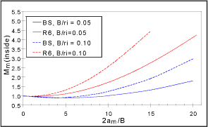
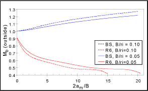
Three examples of geometries where there is considerable difference between existing solutions are given below. Figure 1 shows the solutions for an equatorial through-thickness crack in a sphere:
Fig. 1. K-solution for through-thickness crack in a sphere
|
| a) Membrane stress, outer surface |
b) Membrane stress, inner surface |
 a) Membrane stress, outer surface a) Membrane stress, outer surface |
 |
| c) Bending stress, outer surface |
d) Bending stress, inner surface |
 |
 |
The R6 solution for membrane loading is lower at the outside of the sphere, but higher at the inside, than the BS7910 solution. Under through-wall bending stress, the solutions diverge widely. The R6 solutions[15,16,17] are reasonably consistent with solutions for through-thickness flaws (axial and circumferential) in a cylinder, and are probably more accurate than those of BS7910[18]. The through-thickness flaw in a sphere is one of the geometries currently being examined by TWI on behalf of the R6 committee, and the outcome of the exercise will also be fed back to the appropriate CEN/FITNET committee.
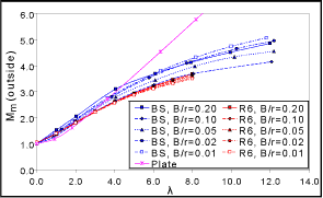
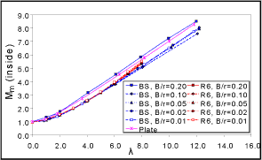
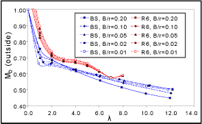
There are also discrepancies between R6 and BS 7910 for the solutions for axial through-thickness flaws in cylinders. The BS 7910 and R6 solutions are shown in Figure 2 (a small error in the BS 7910 source document[19] has been corrected in the course of compiling the FITNET compendium). Particularly under bending (Figure 2c and d), there are discrepancies between the BS 7910 and R6 solutions. Moreover, the R6 solutions for different B/r ratios do not converge as expected as λ approaches zero. These solutions, like those for the through-thickness flaw in a sphere, are under investigation at the time of writing, and results will be made available to CEN/FITNET in due course.
A simplified solution for an axial through-thickness flaw in a cylinder is also included in Figure 2a and b, in which the solution for a through-thickness flaw in a plate is modified by the bulging factor M as follows:
The simplified solution (labelled 'plate') is included in FITNET because it can be applied to cases where the geometry of the component being analysed is outside the validity range, ie 0.01 ≤ B/rm ≤ 0.2, λ<8.0 for R6 solutions, λ<12.2 for BS 7910 solutions. It can be seen from that the simplified solution overestimates the geometry-specific solution considerably at the outer surface and for high values of λ, but may even underestimate it slightly at low values of λ. For the inner surface under membrane loading, the simplified solution follows the same trends as the geometry-specific. Geometry-specific solutions are therefore preferred when the geometry of the component falls within the specified range.
| Fig. 2. K-solution for axial through-thickness crack in a cylinder |
| a) Membrane stress, outer surface |
b) Membrane stress, inner surface |
 |
 |
| c) Bending stress, outer surface |
d) Bending stress, inner surface |
 |
 |
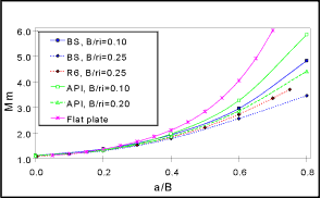
Finally, Figure 3a and b compare the BS7910, R6 and API 579 solutions for an extended axial flaw in a pipe (external and internal flaws respectively). The R6 and API solutions show a higher K-solution for external than for internal flaws, whereas the BS 7910 solutions are identical for internal and external flaws, and should be treated with caution.
| Fig.3. K-solution for extended axial crack in a cylinder |
| a) Membrane stress, external crack |
b) Membrane stress, internal crack |
 |
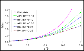 |
A simplified solution based on a flat plate solution multiplied by a bulging factor is also shown for comparison. It overestimates the geometry-specific solutions across the range of a/B, but can be used for geometries outside the range covered by the geometry-specific solutions.
Compilation of limit load solutions
Annex B of FITNET contains a wide range of limit load solutions, based largely on the R6/SINTAP solutions. Most of the geometries are similar to those of Annex A, although there are exceptions. For example, Annex B contains some unique solutions (e.g. limit load solutions for tubular joints), but has fewer solutions for bolts, bars, cylinders and plates than Annex A. Annex B also contains solutions for strength-mismatched materials, 'bi-materials' (adjacent materials of different strength) and clad materials, as summarised in Table 1.
In contrast with the situation observed when collating the K-solutions, the available Lr-solutions do not show many differences between them. There are fewer sources of solutions available, and the main difference between them is in the method of presentation. The most extensive solutions were found in R6[5] and SINTAP[8]. Although SINTAP solutions for Lr have already been incorporated into R6 procedures, the latter contains several additional solutions.
For the case of bending loads, solutions from the SINTAP procedure sometimes express the limit load in terms of an equivalent outer-fibre bending stress, σb L. In most cases, however, the solution for a given case is presented as a limit force value, FN, pressure, Pe, bending moment, Me b, or - in the case of axi-symmetric through wall bending - bending moment per unit angle of wall subtended at the centre of the section, mL and in terms of the parameter Lr.
The solutions are based on a constant membrane and/or through-wall bending stress, and can be readily solved with a calculator or spreadsheet. All available models, e.g. global/local collapse, plane strain/plane stress. Mises/Tresca are collated in Annex B, with the responsibility placed on the user to select the appropriate solution.
Special features of Annex B
There are additional useful Lr-solutions in Annex B to take account of inhomogeneous components, thereby allowing the use of the more advanced levels of fracture analysis. Three different examples of inhomogeneity are considered:
- mismatch: two materials with similar tensile properties are joined by a weld, the tensile properties of which may either be higher than that of the parent material (overmatching) or lower (undermatching). A crack is assumed to be present, either at the weld centreline, or at the weld/parent interface (see Figure 4a).
- bi-material joint: two materials with different tensile properties are joined, and a crack is assumed to be present at the interface between the two (see Figure 4b).
- clad component: here, the crack is assumed to be perpendicular to the clad/parent interface (see Figure 4c).
Fig. 4. Examples of material inhomogeneity in FITNET Annex Ba) Mismatched weld geometries;
FITNET Lr solutions are available for a flaw at the weld centreline (left) or the fusion line (right)
b) Example of a bi-material joint;
FITNET Lr solutions are available for a flaw at the interface between the components, which have dissimilar tensile properties
c) Example of a clad material;
FITNET Lr solutions are available for a through-thickness flaw (left) and for a through-thickness flaw situated at the centre of a repair in the cladding (right)
The solutions for cladding are unique to FITNET; neither R6 nor SINTAP currently contains these solutions. However, bi-material components in the form of clad plates are in practice often used to improve the corrosion resistance of the substrate metal. Cracks developed during service in clad steel plates of pressure vessels can be divided into two major categories: surface cracks in the corrosion-resistant clad layer, and under-clad (sub-clad) cracks. Since surface cracks in the clad layer may grow into the substrate, limiting the service life of these components. Both types of cracks pose potential dangers for the structure, requiring careful inspection and structural assessment against fracture. Furthermore, given that such defective areas may be repaired by welding, the structural significance of repair weld defects of the bi-material components may need to be assessed. Annex B therefore includes solutions developed by Alexandrov[20], and Koçak and Motarjemi [21,22] for the treatment of cracked bi-material plates under tension, with and without repair welds.
Concluding comments
A wide-ranging set of solutions for stress intensity and limit loads is presented in Annexes A and B, based largely on existing FFS procedures (especially R6/SINTAP and BS 7910). Whilst there may be occasions where the user needs to look outside FITNET for an appropriate solution, it is envisaged that most practical cases can be solved from the array of plates, pipes, bars and other geometries offered in FITNET.
Acknowledgments
This work was jointly funded by the European Commission's FITNET Thematic Network (5th Framework Programme, Contract No. G1RT-CT-2001-05071) and the Industrial Members of TWI (as part of the Core Research Programme).
Thanks are also due to Martin Goldthorpe and Liwu Wei for their contributions to the K-solution compilation, and to BSI and British Energy for their co-operation in making available the BS 7910 and R6 documents and background information.
References
- Murakami Y: 'Stress intensity factors handbook' (3 volumes), Pergamon Press, Oxford, 1987-1992
- Tada H, Paris P C and Irwin G: 'The stress analysis of cracks handbook', Third Edition, ASME, New York, 2000.
- Rooke D P and Cartwright D J: 'Compendium of stress intensity factors', HM Stationery Office, London, 1976.
- Sih G C, Paris P C and Erdogan F: 'Stress intensity factors for plane extension and plate bending problems', J Appl Mech 29, 1962, pp 306-312.
- R6: 'Assessment of the integrity of structures containing defects', Rev 4, British Energy, 2001.
- BS 7910:2005: 'Guide to methods for assessing the acceptability of flaws in metallic structures', British Standards Institution, 2005.
- API Recommended Practice 579, Fitness-for-Service, API Publishing Services, First edition January 2000.
- SINTAP (Structural Integrity Procedures for European Industry), Final Procedure, November 1999.
- FKM, 'Bruchmechanischer Festigkeitsnachweis', 2004, also available in English as 'Fracture mechanics proof of strength for engineering components', 2004.
- INSTA Technical Report, 1991: 'Assessment of structures containing discontinuities', Materials Standards Institution, Stockholm.
- RSE-M: Feb 2000: Regles de surveillance en exploitation des materials mecaniques des ilots nucleaires R.E.P.
- IIW: 'IIW guidance on assessment of the fitness for purpose of welded structures', Draft for Development, 1990, IIW/IIS-SST-1157-90
- WES 2805: 'Method of assessment for flaws in fusion welded joints with respect to brittle fracture and fatigue growth'. Japanese Welding Engineering Society, 1997
- Hadley, I, Goldthorpe, M and Wei, L: 'Compilation of K-solutions for fitness-for-service procedures', TWI members' report 849/06
- Smith, M C: 'A comparison of R6 Code SIF solutions for defects in cylinder with other solutions', British Energy Generation Report E/REP/ATEC/0006/GEN/01, 2001.
- Chell G C: 'ADISC: A computer program for assessing defects in spheres and cylinders', CEGB Report TPRD/L/MT0237/M84, 1984.
- Delale F and Ergodan F: 'Effect of transverse shear and material orthotropy in a cracked spherical cap', Int J Solids Structures, 15, 1979, pp907-926.
- Zahoor A: 'Closed form expressions for fracture mechanics analysis of cracked pipes', J Pressure Vessel Technology, 107, N2, 1985, pp203-205.
- France C C, Green D, Sharples J K and Chivers T C: 'New stress intensity factors and crack opening area solutions for through-wall cracks in pipes and cylinders', ASME PVP Conference Fatigue and Fracture 1997, PVP-Vol. 350, pp. 143-193.
- S. Alexandrov, M. Koçak, 'Limit load solutions for bilayer plates with a through crack subject to tension', Engineering Fracture Mechanics 64 (1999) 507-511.
- A K. Motarjemi, M. Koçak, 'Tensile yield load solutions for centre cracked bilayer (clad) plates with and without repair welds', Science and Technology of Welding and Joining, 2002, Vol.7, No 5, 299-305.
- A K. Motarjemi and M. Koçak, 'Fracture assessment of a clad steel using various SINTAP defect assessment procedure levels', 2002 Fatigue Fract Engng Mater Struct 25, 929-939.